

A hydraulic ram can fail in several different ways. It may stop extending completely, retract slowly, drift under load, lose lifting force, move in a jerky motion, or work normally when cold but become weak after the hydraulic oil heats up.
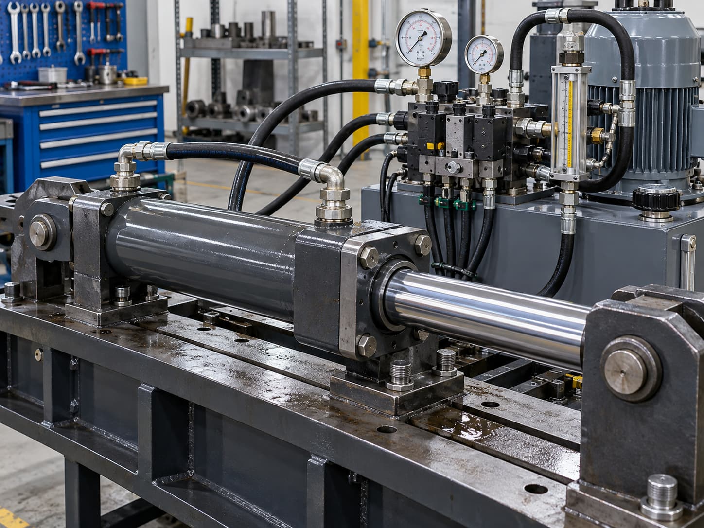
The cylinder itself is not always the root cause.A damaged rod seal can cause obvious external leakage, but low force or slow movement may also come from contaminated fluid, trapped air, an incorrectly operating control valve, pump wear, a blocked suction path, or an electrical fault in the motor or valve controls.
For effective troubleshooting, diagnose the system in a logical order:
visible condition → fluid condition → pressure and flow → valve command → pump performance → cylinder condition
For a broader explanation of how pumps, valves, pressure, flow, and cylinders interact, see how hydraulic systems work. DALLAST's existing guide explains why pressure develops in response to load resistance and how electrical valve commands can be compared with the actual hydraulic response.
Seal Failures and External Hydraulic Leak Identification
Seal failure is one of the first things maintenance teams notice because hydraulic oil around the gland is easy to see. However, identifying oil at the rod end does not explain why the seal failed.
Common mechanisms include:
abrasive wear from contaminated oil or dirt entering past the wiper;
seal extrusion caused by excessive pressure or excessive clearance;
cuts caused during assembly;
heat-related hardening or permanent deformation;
chemical swelling or softening from incompatible hydraulic fluid;
loss of elasticity after prolonged thermal aging;
rod scratches, corrosion, or chrome damage cutting the sealing lip;
side loading that pushes the rod against the bearing and seal.
Cold weather can create another failure pattern. Low temperature increases oil viscosity and can reduce the flexibility of some elastomers, increasing start-up friction. At high temperature, viscosity falls while seal materials may soften or age more quickly.
This matters in U.S. equipment that may operate across very different environments, from northern winter construction and snow equipment to agricultural machinery and lift equipment working through hot summer conditions.
Is it seepage or a serious leak?
Do not rely only on descriptions such as "slightly wet."
A repeatable field check is more useful:
Clean and dry the gland and rod area.
Record hydraulic oil temperature and operating pressure.
Place the machine in the same repeatable operating condition.
Cycle or hold the cylinder for a defined period.
Collect measurable leakage where it can be done safely.
Record leakage in mL/min, or record fluid mass and convert it using the oil density.
Repeat under comparable pressure and temperature.
There is no universal mL/min external-leak limit that applies to every hydraulic cylinder. A value is meaningful only when compared with the OEM acceptance specification, previous baseline, safety requirements, and application.
UV fluorescent dye can also help trace a very small external leak, but the dye dosage should come from the specific dye manufacturer rather than a generic concentration.
A thin residual oil film on the piston rod should also not automatically be confused with seal failure. Dynamic rod sealing depends on controlled lubrication of the sliding surface.
Stop operation when leakage is rapidly increasing, a pressurized spray or pinhole leak is present, the machine cannot hold its load safely, oil is reaching brakes or walking surfaces, or reservoir loss threatens pump operation.Never locate a suspected high-pressure hydraulic leak with a bare hand.
Before servicing, isolate energy, mechanically support loads, and depressurize the circuit. OSHA 29 CFR 1910.147 covers hazardous-energy control in general industry and explicitly includes hydraulic energy, although the standard itself excludes construction and agricultural employment; equipment in those sectors must follow the applicable industry-specific requirements and employer/OEM procedures.
For a deeper seal- and rod-specific diagnosis, link this section to DALLAST's guide to hydraulic cylinder leakage.
Fluid Contamination: Sources, Testing, and Hydraulic Oil Selection
Dirty hydraulic oil can create symptoms that resemble mechanical cylinder failure.
Typical contamination includes external dust, metallic wear debris, water, condensation, fibers, degraded seal material, oxidation products, and debris introduced during maintenance.
A damaged rod wiper is one obvious entry point. Parker also notes that particles can enter through breathers and cylinder rod sealing systems, while pumps, motors, and valves generate additional particles through normal wear. Parker Hannifin Corporation
Environmental exposure changes the risk.
A dusty construction site increases solid contamination. Coastal or humid conditions increase moisture concerns. Repeated northern cold starts can produce high oil viscosity and poor suction conditions until the system reaches operating temperature.
What should an oil test measure?
A useful hydraulic oil analysis normally considers:
| Test | What It Helps Identify |
|---|---|
| ISO 4406 particle count | Solid contamination level |
| Water content | Moisture ingress or condensation |
| Viscosity | Wrong oil, degradation, contamination, temperature-related problems |
| Total Acid Number (TAN) | Fluid aging/oxidation trend |
| Wear metals | Component wear trends |
| Visual appearance | Cloudiness, foam, free water, debris |
Commercial oil-analysis programs commonly evaluate viscosity, water, TAN, elemental wear data, and particle counts together rather than judging fluid condition from color alone.
Use a properly designed sampling point where possible. Do not take a sample by loosening a pressurized fitting. Consistency is critical: sampling location, machine condition, temperature, bottle cleanliness, and flushing procedure can otherwise distort the trend.
What ISO cleanliness level should you use?
There is no single ISO 4406 target for all hydraulic systems.As an example, Parker describes 20/18/15 as suitable for relatively general or lower-pressure service in one engineering reference, while recommending 18/16/13 where pressure, life, or functional requirements are more demanding. Some proportional-valve products require even cleaner fluid.
The correct target should therefore come from the most contamination-sensitive component in the actual circuit.
Legacy equipment documents may also specify NAS cleanliness classes. When possible, keep trending in one consistent system rather than casually converting between classifications.
ISO VG 32 or ISO VG 46?
Do not select hydraulic oil from climate alone.ISO VG 32 has lower nominal viscosity at 40°C than ISO VG 46, so it may help achieve an acceptable operating viscosity at lower temperatures. However, the pump, valves, seals, maximum operating temperature, viscosity index, and OEM approval must all be considered.
For example, one Parker piston-pump manual specifies a normal operating viscosity range of 16–100 cSt, with an optimum range around 20–40 cSt, while allowing much higher viscosity only briefly. That illustrates why very viscous oil during a cold start can affect pump filling and system response. Parker Hannifin Corporation
Send the oil to a laboratory when failures repeat, the fluid type is uncertain, water is suspected, metallic debris appears, viscosity has changed substantially, or contamination cannot be explained by field particle testing alone.
Pressure Loss Diagnostics, Air Entrainment, and Bleeding
A ram that will not lift its rated load does not necessarily have a worn piston seal.
Start by determining whether the system produces the required pressure and flow.
Use only properly rated test ports and instruments.
For a static test, bring the actuator to a defined loaded condition and observe whether pressure and position remain stable after the valve command stops. Pressure loss can result from cylinder bypass, valve leakage, load-holding valve problems, or another circuit path.
For a dynamic test, observe pressure while the ram moves under a known load.
Useful test locations may include:
pump outlet → valve inlet → valve work port → cylinder port
If pump outlet pressure and flow are satisfactory but the expected work-port response is missing, investigate the directional valve, pilot circuit, relief path, or electrical command.
If pump output itself is low, move upstream toward the reservoir, suction circuit, pump drive, and prime mover.
There is no universal "acceptable pressure drop" across all valves and hydraulic circuits. Compare readings with the component data sheet and machine specification at the same oil temperature and flow.
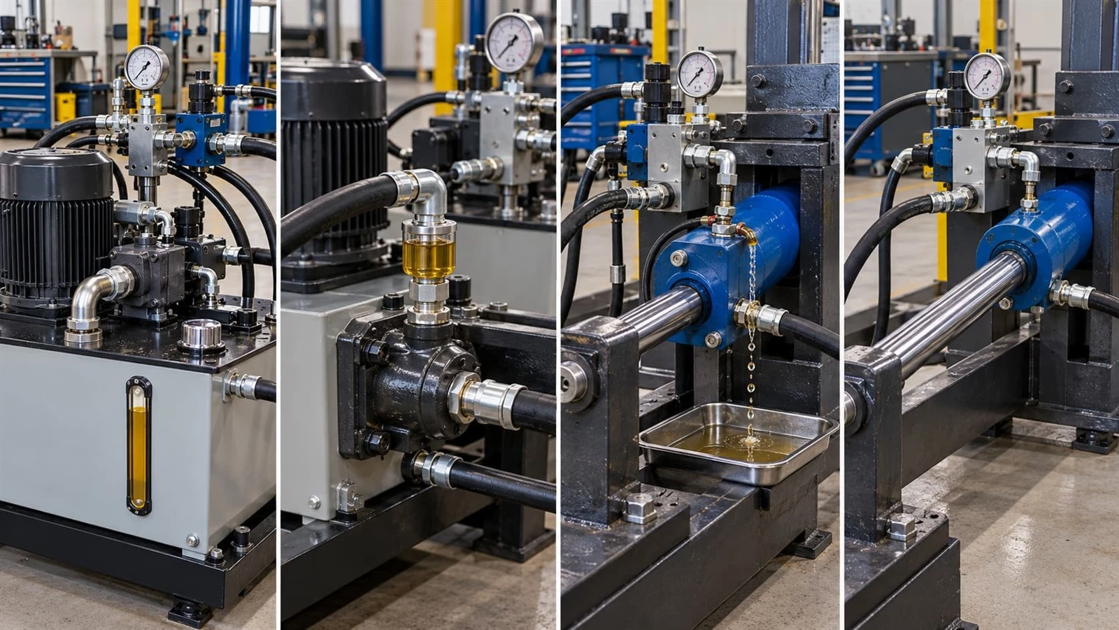
How trapped air affects a hydraulic ram
Air entrainment can cause:
spongy or spring-like motion;
jerky cylinder travel;
delayed response;
unusual pump noise;
unstable pressure;
foaming in the reservoir;
excessive heat.
Possible sources include suction-line leaks, low reservoir level, turbulent tank return, poor deaeration, maintenance work that opened the system, or oil that already contains entrained air.
A general bleeding sequence is:
Mechanically secure the machine and verify the reservoir level.
Inspect suction plumbing and fittings for potential air entry.
Prime the pump according to its manufacturer's procedure.
Start the system unloaded or at the specified low-pressure condition.
Operate the cylinder slowly through partial strokes.
Progress toward complete strokes after motion becomes stable.
Use dedicated bleed points only where the cylinder/system manufacturer provides them.
Recheck the reservoir level as trapped air is displaced.
Continue until movement, oil appearance, and noise stabilize.
Recheck operating pressure and temperature.
Never loosen a high-pressure hose or fitting as an improvised bleeding method.
Closed-loop hydrostatic circuits require particular caution. Charge circuits, case drains, flushing valves, and pump/motor filling procedures differ from conventional open hydraulic circuits, so they should be bled using the specific pump and machine manufacturer's procedure rather than this generic sequence.
Control Valve, Pump, and Motor Failures: How to Separate the Fault
When a hydraulic ram suddenly stops moving, technicians sometimes replace the cylinder before confirming whether hydraulic power is reaching it.
A better approach is to compare the command with the hydraulic response.
| Symptom | First Components to Check |
|---|---|
| No cylinder movement and no pressure rise | Pump drive, motor, coupling, pump inlet, valve command |
| Pressure rises but cylinder does not move | Mechanical load, blocked flow path, valve state, cylinder damage |
| Slow motion in both directions | Pump flow, oil viscosity, filter restriction, pump wear |
| Slow motion in one direction | Directional/flow valve, port restriction, cylinder-side issue |
| Jerky movement | Air, contamination, sticking spool, mechanical binding |
| Ram drifts under load | Cylinder piston seal, directional valve, load-holding valve |
| Pump noisy and pressure unstable | Suction restriction, aeration, cavitation, low oil level |
| Motor overheats/trips | Electrical supply, overload, pump load, mechanical drive condition |
For electrohydraulic equipment, check whether the PLC or controller is actually requesting valve movement.
DALLAST's hydraulic-system guide notes that technicians can compare an electrical command with measured hydraulic response: if the command reaches the solenoid but hydraulic pressure does not respond, the investigation moves toward the solenoid, spool, pilot supply, and hydraulic source; if there is no electrical command, begin with wiring, interlocks, sensors, or the controller.
Qualified personnel can also compare:
motor supply voltage and current;
commanded versus actual motor speed;
pump outlet pressure and flow;
pump shaft/coupling condition;
abnormal pump vibration;
valve coil command/current;
pressure before and after the valve.
Avoid improvised bypass hoses or unauthorized valve isolation. Diagnostic manifolds, flow meters, test ports, and isolation devices must be rated for the circuit and used according to an approved test procedure.
This component-by-component method helps determine whether the repair belongs to the electrical controls, pump, valve block, or hydraulic cylinder before unnecessary parts are replaced.
Preventive Maintenance and the Repair-vs-Replace Decision
A practical maintenance plan is based on operating severity rather than a fixed universal calendar.
| Interval | Example Checks |
|---|---|
| Every shift / before use | Visible leaks, rod damage, oil level, unusual noise, hoses, cylinder movement |
| Monthly | Pins/mounts, alignment, wipers, filter indicators, reservoir breather, temperature and pressure trends |
| Quarterly or semiannually | Oil analysis based on criticality, particle count, water, viscosity, condition trends |
| Annual / planned shutdown | Baseline pressure/flow tests, deeper cylinder inspection, reservoir condition, controls/instrument verification |
Parker recommends periodic fluid-condition testing and, in one industrial hydraulic reference, suggests checking properties including neutralization number, viscosity, color, and cleanliness at least twice per year. Actual intervals should still be adjusted to machine duty and OEM requirements. Parker Hannifin Corporation
Filter replacement should preferably follow differential-pressure indication, oil-analysis data, and manufacturer instructions rather than an arbitrary date.
The same applies to cylinder seals. There is no universal safe rule such as "replace every 2,000 hours.
Choosing replacement seals
Seal pressure capability cannot be determined by polymer alone; profile, extrusion gap, geometry, backup rings, surface finish, speed, and pressure all matter.
As general selection guidance:
NBR is widely used with mineral/petroleum hydraulic oils and offers good wear resistance.
Polyurethane is frequently selected for dynamic hydraulic seals because of strong abrasion and extrusion resistance.
FKM can support elevated temperatures and many oils, but compatibility must be checked against the specific fluid.
specialty low-temperature compounds may be necessary for severe winter service.
For perspective, Parker's heavy-duty cylinder literature lists one standard seal system for mineral hydraulic oil from approximately -10°F to +165°F, while a specified fluorocarbon system extends to approximately +300°F. Parker's proprietary polyurethane families have different temperature capabilities again. These are product-specific examples, not universal material ratings.
Repair the ram or replace it?
Use physical condition and total ownership cost together.
| Condition | Typical Decision Direction |
|---|---|
| Seal wear, major parts otherwise in specification | Reseal/rebuild |
| Light recoverable rod surface damage | Evaluate polishing or rod refinishing |
| Deep scoring through the rod coating | Re-chrome or replace rod after dimensional inspection |
| Bent rod or severe corrosion | Replacement rod or complete cylinder evaluation |
| Deep barrel scoring / excessive bore wear | Machine-shop evaluation; replacement may be more economical |
| Cracked mount, barrel, or structural weld | Remove from service and obtain qualified structural assessment |
| Multiple repeat failures | Investigate design/application before another identical repair |
| Obsolete cylinder and uncertain remaining life | Compare engineered replacement with rebuild cost |
Avoid using one scratch-depth number as a universal rejection criterion. Rod-coating thickness, seal travel, base-metal damage, final diameter, surface finish, and load determine whether the component can be restored.
For purchasing decisions, an organization can also establish an internal economic threshold. For example, if all-in repair cost plus downtime approaches 60–70% of the landed price of a new cylinder while the repaired barrel, rod, or mountings still have uncertain residual life, requesting a replacement quotation is reasonable. This is a procurement screening rule, not a safety or engineering acceptance standard.
When replacement dimensions need to be captured, use DALLAST's hydraulic cylinder measurement guide.
Used hydraulic oil must also be handled correctly. EPA's federal used-oil management standards are contained in 40 CFR Part 279, and EPA notes that individual states may impose stricter requirements.
When Troubleshooting Points to Cylinder Replacement
If pressure and flow reach the actuator correctly but inspection confirms severe rod damage, barrel wear, structural damage, unsuitable dimensions, or repeated cylinder failure, the next step may be an engineered replacement rather than another temporary repair.
DALLAST manufactures industrial hydraulic cylinders and publicly lists OEM/ODM capability for industrial and long-stroke cylinder applications. Its single- and double-acting hydraulic cylinder category also supports customized cylinders for industrial, agricultural, construction, and mobile equipment.
Frequently Asked Questions
What are the most common causes of hydraulic ram failure?
Common causes include damaged seals, contaminated or unsuitable fluid, air entrainment, insufficient system pressure or flow, sticking control valves, pump wear, electrical/control faults, rod or barrel damage, and mechanical misalignment. Diagnose the hydraulic system before assuming the cylinder itself has failed.
How can I tell whether a seal failure is causing pressure loss?
External oil around the gland indicates an external sealing problem, but pressure loss without visible oil may involve the piston seal or a leaking valve. Measure pressure at approved test points and rule out valve leakage before disassembling the cylinder.
What are the main signs of contaminated hydraulic oil?
Visible particles, cloudy or milky oil, foaming, unusual valve behavior, accelerated seal wear, filter alarms, and abnormal wear debris are warning signs. Particle count, water content, viscosity, TAN, and wear-metal analysis provide better evidence than appearance alone.
How do I diagnose hydraulic pressure loss with a gauge?
Measure pressure progressively from the pump outlet toward the valve and cylinder using rated test points. Compare static holding pressure and dynamic working pressure with the machine specification. There is no universal pressure reading that proves a cylinder failure; the pattern across the circuit is more useful than one gauge value.
What causes air entrainment, and how should a hydraulic system be bled?
Air can enter through pump suction leaks, low reservoir level, maintenance work, poor tank return design, or aerated oil. Correct the air source first, then follow the manufacturer-approved priming and bleeding sequence while operating at low pressure and low speed. Never bleed a system by randomly loosening a pressurized fitting.
Why does my hydraulic ram move slowly or jerk?
Slow movement can result from inadequate pump flow, excessive cold-oil viscosity, filter or valve restrictions, internal leakage, or mechanical binding. Jerky motion more often points toward trapped air, contamination, a sticking valve, unstable controls, or side loading.
When should I repair rather than replace a hydraulic ram?
Repair generally makes sense when seals and replaceable wear parts have failed but the rod, barrel, mounts, and pressure-containing structure remain serviceable. Replacement becomes more attractive when structural damage, severe wear, repeated failure, obsolete parts, or total rebuild cost create unacceptable reliability or downtime risk.