


Hydraulic cylinder stroke length cannot be selected independently from the mounting arrangement.
Two cylinders can have the same bore, rod diameter, working pressure, and 60-inch stroke yet have very different resistance to rod buckling because the mounting style changes the effective column length, the way the load is guided, and the bending moment transmitted into the piston rod.
This becomes especially important in long-stroke cylinders, presses, lifting equipment, agricultural machinery, dump systems, material-handling machines, and other applications where the rod operates under compression.
The engineering relationship is:
Mounting style → load path → effective buckling length → rod diameter / stroke capability → bearing and seal life
For basic dimensions that should be recorded before evaluating an existing cylinder, see DALLAST's hydraulic cylinder measurement guide. The current guide separates stroke, mounting-center dimensions, pin sizes, flange geometry, and rod dimensions rather than treating bore and stroke as sufficient specification data.
Comparing Hydraulic Cylinder Mounting Styles: Side Loads, Moments, and Stroke Effects
The first design question is not simply "Which mount fits the machine?" It is:Does the cylinder remain stationary, or must it rotate as the mechanism moves?
Rigid mounts such as front/rear flanges and foot mounts work best when the load remains accurately aligned with the cylinder centerline. Pivot mounts such as clevises and trunnions allow the cylinder body to change angle as the mechanism moves.
DALLAST's welded-cylinder category similarly separates fixed mounting from pivot mounting and notes that flange mounts suit straight-line force transfer while clevis, trunnion, and spherical-bearing arrangements accommodate pivoting mechanisms.
| Mounting Style | Load-Path Characteristic | Misalignment Capability | Side-Load Design Approach | Long-Stroke Consideration |
|---|---|---|---|---|
| Front/rear flange | Rigid, near cylinder centerline | Low | Do not intentionally use rod as a guide | Can provide favorable buckling geometry when load is rigidly guided |
| Foot / side lug | Rigid but attachment may be offset from centerline | Low | Mount reaction can create overturning moment; machine guiding is important | Long cylinders may require additional support |
| Clevis / pin eye | Pivots in one plane | Good in designed pivot plane | Allows angular movement, but does not make rod a radial bearing | Effective buckling length depends strongly on rod-end guidance |
| Trunnion | Cylinder rotates about barrel-mounted pivot | Good in one plane | Pivot position changes load path and effective length | Trunnion position can materially change buckling behavior |
| Spherical bearing | Allows limited multi-axis angular movement | Better than plain clevis | Bearing rating and permissible angle are manufacturer-specific | Useful where small unavoidable angular variation exists |
| Guided / rodless actuator | Carriage designed to carry external loads | Product-specific | May have published pitch/roll/yaw moment ratings | External support spacing becomes part of actuator sizing |
A useful engineering rule for conventional piston-rod cylinders is therefore:
Design intentional radial rod load as zero unless the selected manufacturer explicitly provides a side-load rating for that cylinder configuration.
Parker states that piston rods are normally not designed to absorb loads perpendicular to their direction of motion or associated bending moments. Parker Hannifin Corporation
This does not mean side-load data never exists. It means it is product-specific.
For example, Parker's P1X pneumatic rodless cylinder publishes explicit carriage ratings:
| P1X Bore | Maximum Standard Load | Pitch Moment | Roll Moment | Yaw Moment |
|---|---|---|---|---|
| 16 mm | 141 N | 5 N·m | 1 N·m | 1 N·m |
| 32 mm | 616 N | 36 N·m | 10 N·m | 21 N·m |
| 63 mm | 2,297 N | 275 N·m | 52 N·m | 76 N·m |
The same catalog gives maximum unsupported lengths at maximum load of approximately 450 mm for the 16-mm bore, 749 mm for 32 mm, and 1,600 mm for 63 mm. Those figures illustrate what a genuine manufacturer side-load specification looks like; they must not be transferred to a conventional hydraulic cylinder or another rodless design.
For fixed hydraulic applications, a flange mount hydraulic cylinder is therefore most appropriate when the machine can maintain a straight axial load path. For mechanisms that rotate throughout the stroke, clevis, trunnion, or spherical arrangements usually provide better kinematic compatibility.
Stroke Limits, Rod Buckling, and Intermediate Support Calculations
The primary mechanical risk for a long piston rod under compression is column buckling.
For an ideal elastic column, Euler's equation is:
Pcr = π²EI / (KL)²
where:
Pcr = Euler critical buckling load
E = Young's modulus
I = second moment of area
L = unsupported physical length
K = effective-length factor determined by end restraint
For a solid circular piston rod:
I = πd⁴ / 64
and the radius of gyration is:
r = √(I/A) = d/4
Therefore the slenderness ratio is:
λ = KL / r = 4KL/d
This explains why rod diameter has such a strong influence: bending stiffness varies with the fourth power of diameter.
Worked example: 2-inch rod with 60-inch effective unsupported length
Assume:
rod diameter = 2.00 in
unsupported physical length = 60 in
steel modulus E ≈ 30 × 10⁶ psi
pinned-pinned approximation K = 1.0
Rod second moment:
I = π × 2⁴ / 64 = 0.785 in⁴
Then:
Pcr = π² × 30,000,000 × 0.785 / 60²
Pcr ≈ 64,600 lbf
If an engineer uses an illustrative buckling design factor of 3.0, rather than treating Euler load as an allowable working load:
64,600 / 3 ≈ 21,500 lbf
This 3.0 factor is an example for demonstrating the calculation-not a universal hydraulic-cylinder requirement. Final safety factors must follow the applicable manufacturer, design standard, load uncertainty, fatigue conditions, and consequence of failure.
Now change only the boundary condition.
Using an approximate fixed-pinned factor of K = 0.7:
Pcr ≈ 131,800 lbf
Using a cantilever-like K = 2.0:
Pcr ≈ 16,150 lbf
The rod material and diameter have not changed, but the theoretical buckling load changes by more than eight times between those two idealized end conditions.
This is the fundamental relationship between mounting style and permissible stroke.
Industrial cylinder manufacturers often handle the same issue through stroke factors rather than requiring customers to perform pure Euler calculations. Parker's hydraulic HMI selection data, for example, assigns stroke factors from 0.5 to 3.0 depending on the cylinder mount and whether the rod-end load is fixed, pivoted, rigidly guided, or unsupported. It then uses:
Basic Length = Actual Stroke × Stroke Factor
for rod/stroke selection. Parker Hannifin Corporation
Parker's very-heavy-duty hydraulic catalog also gives factors including 0.50, 0.70, 1.00, 1.50, and 2.00 for different mounting/guidance combinations and specifically recommends considering intermediate support on horizontally mounted long-stroke cylinders. Parker Hannifin Corporation
Calculating a maximum effective unsupported length
Euler's equation can also be rearranged.
If the design requires:
Pcr ≥ SF × Fcompression
then:
Lmax = (π/K) × √[EI / (SF × Fcompression)]
This is more defensible than a generic rule such as "support the cylinder every X times the bore diameter."
For example, if rod diameter, expected compression force, end restraint, and required design factor are known, the equation provides the maximum effective rod column length for preliminary screening.
It does not automatically determine barrel support spacing. Horizontal barrel deflection, mount reaction, stop-tube requirements, bearing pressure, machine-frame stiffness, and the cylinder manufacturer's design still require separate checks.
Stop tubes are another important tool. Parker recommends them on long-stroke cylinders because increasing the distance between piston and gland at full extension reduces bearing loading and improves stability. Parker Hannifin Corporation
For applications where long travel is unavoidable, DALLAST has a dedicated long-stroke hydraulic cylinders category intended for custom long-travel industrial configurations. The final rod, mounting, and support design should still be based on the actual load case rather than stroke length alone.
Telescopic versus conventional cylinders
A telescopic cylinder solves a different problem: obtaining a long stroke from a short retracted envelope.
However, each extending stage progressively changes its unsupported length, section diameter, bending stiffness, overlap, and bearing geometry. It should therefore be checked stage by stage rather than applying one conventional single-rod Euler calculation to the entire actuator.
Pneumatic cylinders usually develop much lower axial forces than similarly sized hydraulic cylinders because operating pressure is much lower, but long pneumatic rods can still buckle. The same mounting and guidance principles remain relevant.
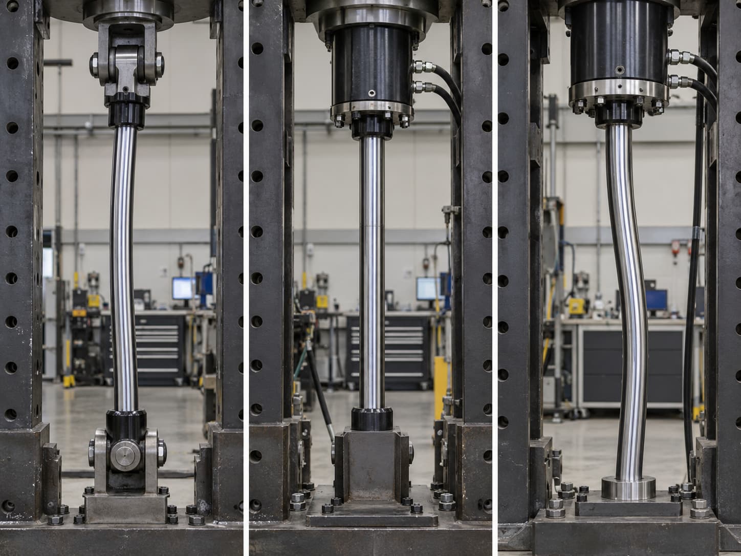
Angular Misalignment, Bending Moments, and Dynamic Fatigue
Even a small angular error can become a large lateral displacement on a long cylinder.
The lateral offset created by an angular mismatch is approximately:
δ = L × tan θ
For a 60-inch effective length and only 0.25° of angular error:
δ = 60 × tan(0.25°) ≈ 0.262 in
A quarter degree can therefore attempt to force the rod more than a quarter inch away from its natural centerline over a 60-inch span.
That is why a rigid flange cylinder should not be bolted into a bracket arrangement that requires the rod to bend sideways just to connect the rod-end pin.
Side force creates bending moment:
M = Fside × e
where e is the moment arm.
Suppose a misaligned mechanism develops a 250-lbf lateral force acting 12 in from the critical rod section:
M = 250 × 12 = 3,000 lbf·in
For a solid 2-in-diameter rod, nominal bending stress is:
σb = 32M / (πd³)
σb ≈ 3,820 psi
If a transient impact temporarily doubles the lateral reaction, bending stress rises to approximately 7,640 psi, in addition to the axial cylinder stress.
Those stresses can become particularly important at rod threads, diameter transitions, grooves, welded attachments, or other stress concentrations.
Dynamic and fatigue loading
A static force calculation is not enough when the cylinder cycles repeatedly.
An engineering fatigue review should consider:
minimum and maximum cylinder force during each cycle;
acceleration and deceleration loads;
pressure spikes;
reversed bending;
load eccentricity;
cycle frequency and expected lifetime;
stress concentration factors;
material S-N data;
weld or thread geometry.
Rexroth specifically distinguishes quasi-static from dynamic loading and notes that allowable load ratings for swivel components can decrease under alternating loads; those ratings are manufacturer-specific rather than standardized across all rod ends. Bosch Rexroth Global
End-of-stroke cushioning should also be considered from kinetic energy:
Ek = ½mv²
Higher speed increases energy with the square of velocity, so doubling cylinder speed produces four times the kinetic energy that must be stopped.
For fast machines, select cushion length and deceleration characteristics using moving mass, actual velocity, mechanism geometry, and cycle rate. Do not use a cushion merely to compensate for an undersized structural mount or uncontrolled external load.
Selection, Installation, CAD, and Maintenance Best Practices
For an OEM project, select the mounting configuration only after defining the complete machine motion.
Start with required pushing and pulling force, pressure, stroke, retracted length, speed, duty cycle, orientation, load direction, and whether the cylinder or rod-end attachment must rotate.
A rigid flange or foot mount should keep the load axis coincident with the cylinder axis. Pivoting mechanisms should normally use compatible pivots at the cylinder and load attachment so the ram does not become the machine's guide member.
Do not publish a universal pin clearance, flange-bolt torque, or allowable angular error. These values depend on pin diameter, bushing design, bolt grade, lubrication, mount material, cylinder force, and fatigue loading.
For fastener design, the simplified relationship:
T ≈ K × Fpreload × D
can be used during engineering, but the nut factor K changes significantly with lubrication, coating, and thread condition. Final torque therefore belongs in the approved drawing or manufacturer installation specification.
Practical alignment check
During installation:
Position and support the cylinder without using bolts or pins to pull a misaligned structure into place.
Confirm base and rod-end pivot centers from the CAD or machine drawing.
Check the mechanism in retracted, mid-stroke, and extended positions.
Use a dial indicator, straightedge, laser alignment equipment, or machine datum surfaces where appropriate.
Confirm pins rotate or articulate as intended rather than binding.
Verify hose routing throughout the complete cylinder movement.
After commissioning, inspect rod seals, guide wear, pins, bushings, flange bolts, and mounting welds for evidence of abnormal side loading.
The exact acceptable alignment tolerance should come from the cylinder/machine design. The 0.25° example above demonstrates why assigning a loose generic angular tolerance to a long rigidly mounted cylinder can be misleading.
CAD parameters that should be included
For a useful cylinder assembly model, parameterize:
bore, rod diameter, stroke, retracted mount-center distance, extended length, base pivot, rod-end pivot, flange or trunnion geometry, pin diameters, rod extension, stop-tube length, port orientation, and swept motion envelope.
Model the entire mechanism at full retract and full extension, not only the cylinder as a static solid.
Parker's current 2D/3D cylinder configurator follows this approach: its CAD models allow the rod to extend and retract so designers can examine motion constraints and dimensions at different positions.
For replacement projects, DALLAST's How Do You Measure a Hydraulic Cylinder guide also identifies pin-center length, trunnion position, flange pattern, mounting offsets, ports, bore, rod, and stroke as separate RFQ dimensions.
Specify a Long-Stroke or Custom-Mounted Hydraulic Cylinder
For an OEM cylinder with an unusual stroke, mounting arrangement, pivot geometry, or compression load, do not send only bore × stroke × pressure.
A useful engineering RFQ should include required extension/retraction force, maximum pressure, stroke, retracted center distance, rod-end guidance, mounting style, pivot locations, load direction, maximum side or eccentric load, cylinder orientation, speed, cycle rate, duty cycle, environmental conditions, and 2D/3D machine drawings.
DALLAST's single- and double-acting hydraulic cylinder category confirms customization around bore, rod, stroke, mounting style, mounting distance, pressure, ports, and customer drawings.
For applications specifically involving a rigid straight-line load path, the flange mount hydraulic cylinder page is a relevant commercial destination. Long-travel projects can instead be directed to the long-stroke hydraulic cylinder range.
FAQ
How do I calculate hydraulic-cylinder rod buckling?
Use the Euler relationship Pcr = π²EI/(KL)² for preliminary elastic-column screening, with the correct rod moment of inertia and effective-length factor. Compare the critical load with expected compression force using an appropriate design factor. For production selection, also follow the cylinder manufacturer's buckling method or NFPA/T3.6.37 rather than relying on Euler alone.
What side load is acceptable for flange, foot, clevis, or trunnion cylinders?
There is no valid universal N or N·m value based only on mounting style. Conventional piston rods are generally intended to transmit axial force, and Parker specifically warns against unaccounted perpendicular loads and bending moments. If the application requires external moment capacity, use a guided actuator or obtain a manufacturer-specific side-load calculation.
How do I calculate support spacing for a long-stroke cylinder?
For rod buckling, rearrange Euler's equation to calculate maximum effective unsupported length:
Lmax = (π/K) × √[EI/(SF × Fcompression)]
Horizontal barrel support spacing must also be checked for barrel deflection, mount loading, stop-tube requirements, alignment, and machine-frame stiffness. There is no reliable universal spacing based on bore diameter alone.
How do pneumatic, hydraulic, and telescopic cylinders differ for long strokes?
Hydraulic cylinders normally produce much higher compression forces, making rod buckling especially important. Pneumatic cylinders have the same column-stability issue but generally lower axial forces. Telescopic cylinders require stage-by-stage stability analysis because each stage has a different diameter, overlap, and unsupported length.
How should angular misalignment be included in cylinder design?
Calculate geometric offset using δ = L tan θ, determine any resulting side force from the mechanism, then calculate bending moment with M = Fside × e. For dynamic equipment, add acceleration, impact, pressure transients, load spectra, and fatigue effects rather than checking only static alignment.
What installation tolerances should be used for a long-stroke cylinder?
Use the approved cylinder and machine drawing rather than a generic angular or radial tolerance. Check alignment throughout the complete stroke, ensure rigid mounts follow the load centerline, verify pivot joints can articulate freely, and measure wear or displacement trends during scheduled maintenance.