

Measuring a hydraulic cylinder correctly is essential when ordering a replacement cylinder, rebuilding an existing unit, matching seals, or verifying whether a cylinder can meet the force and stroke requirements of a machine.
A few basic dimensions-such as bore, rod diameter, stroke, and mounting length-are important, but they are not enough for many replacement projects. You may also need to record mounting geometry, pin sizes, hydraulic port threads, operating pressure, seal dimensions, and application conditions.
If you are replacing an unfamiliar cylinder, identifying the correct type of hydraulic cylinder before taking measurements can help determine which dimensions, mounting details, and operating information need to be recorded.
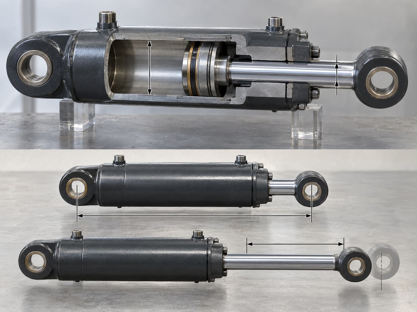
Before measuring or disassembling a hydraulic cylinder, isolate the machine from its energy sources, lower or mechanically support suspended loads, relieve stored hydraulic pressure, and follow the applicable lockout/tagout procedure. OSHA specifically requires hazardous stored energy, including hydraulic pressure, to be relieved, restrained, or otherwise made safe before servicing equipment.
Measuring Core Cylinder Dimensions: Bore, Rod, Stroke, and Retracted Length
Start with the four dimensions that define most hydraulic cylinders:
Bore diameter
Piston rod diameter
Stroke length
Retracted or closed length
1. How to Measure Hydraulic Cylinder Bore
The bore is the inside diameter of the cylinder barrel and determines the effective piston area.
If the cylinder is disassembled, measure the bore with an:
Inside micrometer
Dial bore gauge
Inside caliper
Precision telescoping gauge
Take readings at several positions around the circumference and at multiple depths. This can reveal taper, scoring, or out-of-round wear.
Do not use the outside barrel diameter as the bore measurement. Wall thickness varies considerably between cylinder designs.
If the cylinder cannot be disassembled, you normally cannot obtain a reliable direct bore measurement. Instead, look for:
Manufacturer model number
Nameplate information
Original engineering drawing
Parts manual
Piston or gland dimensions from a known cylinder series
The barrel outside diameter can provide a rough clue, but it should not be treated as the final replacement specification.
2. Measure the Piston Rod Diameter
Measure the polished rod with an outside micrometer or quality digital/vernier caliper.
Take measurements in several locations, particularly where the rod passes through the gland during normal operation.
For example, record:
Rod Diameter: 2.000 in / 50.80 mm
Avoid measuring over rust, chrome damage, paint, or contamination.
Rod diameter matters for more than replacement fit. It changes the effective area on the rod side of a double-acting hydraulic cylinder and therefore affects retraction force.
3. Measure Stroke Length
Stroke is the distance the piston travels from fully retracted to fully extended.
One practical method is:
Stroke = Extended reference length − Retracted reference length
Choose the same two reference points for both measurements.
For example:
Retracted pin-to-pin length: 36 in
Extended pin-to-pin length: 60 in
Stroke: 24 in
Do not confuse stroke with exposed rod length. Rods often include threaded ends, shoulders, clevises, or unused length that is not part of the working stroke.
4. Measure Retracted Length
For replacement cylinders, pin-center-to-pin-center distance is often more useful than total physical length.
With the cylinder fully retracted, measure from the center of one mounting pin to the center of the opposite mounting pin.
Also record:
Overall retracted length
Extended length
Pin-to-pin retracted length
Pin-to-pin extended length
Always state whether measurements are in inches or millimeters.

For precision dimensions such as bore and rod diameter, a micrometer is preferable. Large mounting dimensions can usually be recorded with a steel rule or tape measure, but do not assume a universal manufacturing tolerance. Replacement-cylinder tolerances should be confirmed against the original drawing or manufacturer specification.
Bore diameter is especially important because hydraulic cylinder force is based on pressure multiplied by effective piston area.
Identifying Mounting Dimensions, Ports, and Thread Sizes
A replacement cylinder can have the correct bore and stroke and still fail to fit if the mounting geometry is wrong.
First identify the mounting style.
Common configurations include:
Clevis mount
Cross-tube or pin-eye mount
Flange mount
Foot mount
Trunnion mount
Spherical bearing mount
Welded mounting lug
For pin-mounted cylinders, record:
| Measurement | What to Record |
|---|---|
| Pin Diameter | Actual pin or mounting bore diameter |
| Pin-to-Pin Length | Center-to-center distance when retracted |
| Lug Width | Width of mounting eye or clevis |
| Inside Clevis Width | Available space between clevis ears |
| Mounting Hole Diameter | Finished hole or bushing ID |
| Offset | Distance between cylinder centerline and mount centerline |
For flange cylinders, measure flange thickness, bolt diameter, bolt-hole spacing, pilot diameter, and bolt-circle dimensions where applicable.
For trunnion cylinders, record the trunnion diameter, location along the barrel, width between supports, and distance from the cylinder reference point to the trunnion centerline.
How to Identify Hydraulic Port Threads
Do not identify a port simply by measuring its approximate diameter.
Common hydraulic connections include:
NPT/NPTF
SAE straight thread or UN/UNF
JIC
BSPP
BSPT
Metric threads
ORFS
Thread-identification guidance recommends checking multiple characteristics because BSP, metric, and American hydraulic threads can have similar diameters. You should compare thread diameter, thread pitch, whether the thread is tapered or parallel, and the sealing or seat geometry.
Use:
Digital calipers
Thread pitch gauge
Seat-angle gauge
Thread identification chart
For NPT connections, measure the male outside diameter or female inside diameter at the appropriate full thread and verify the threads per inch.
Also record the port location and orientation-for example:
Cap-end port: SAE -08, 90° upward
Rod-end port: SAE -08, 90° upward
If available, photograph the cylinder nameplate. Model numbers can help identify working pressure, temperature limitations, seal material, and original configuration.
Assessing Cylinder Condition: Seals, Rod Straightness, and Wear
If the cylinder is being rebuilt rather than replaced, dimensional inspection should include its condition.
Identify and Measure Hydraulic Seals
Common cylinder seals include:
U-cup seals
O-rings
V-packing
Piston seals
Rod seals
Wear rings
Wipers or scrapers
Do not order a seal based only on its outside diameter.
Record:
Seal type / ID / OD / width / groove dimensions / material if known
For example:
Rod Seal – U-Cup – 2.000 in ID × 2.500 in OD × 0.375 in Width
Take clear photographs beside a scale or caliper. Also photograph the gland and seal groove.
Check Rod Straightness
A bent rod can damage seals and guide bearings even after new seals are installed.
For a removed rod, support it on suitable V-blocks and rotate it while monitoring the surface with a dial indicator.
Record the maximum indicated variation and the measurement location.
A specific acceptable runout limit should come from the cylinder manufacturer or repair specification because allowable values depend on rod diameter, length, design, and application.
Inspect Barrel and Piston Wear
Check for:
Longitudinal scoring
Pitting
Corrosion
Abnormal polishing
Bore taper
Out-of-round conditions
Damaged piston wear bands
Metal contamination
When complete disassembly is not practical, a borescope may help identify obvious internal surface damage. Pressure or leakage testing can also help distinguish external seal leakage from internal piston-seal bypass, although it does not replace dimensional inspection when rebuilding the cylinder.
Document damaged areas with photographs and mark their approximate location from the cap or gland end.
Measuring Telescopic and Special-Case Hydraulic Cylinders
Telescopic hydraulic cylinders require more information because several moving stages contribute to the total stroke.
Record:
Fully retracted length
Fully extended length
Total stroke
Number of stages
Outside diameter of each exposed stage
Exposed travel of each stage
Mounting dimensions
Port locations
Extension sequence
Do not assume that all stages travel the same distance.
A useful field record might look like this:
| Stage | Diameter | Measured Travel |
|---|---|---|
| Stage 1 | 4.50 in | 24 in |
| Stage 2 | 3.75 in | 23 in |
| Stage 3 | 3.00 in | 22 in |
Also note whether the cylinder is single acting or double acting.
For a single-acting hydraulic cylinder, document how the cylinder returns-gravity, external load, or spring assistance.
For a double-acting cylinder, photograph and identify both hydraulic ports and record whether cushioning, counterbalance valves, pilot-operated check valves, or other integrated components are present.
For replacement or rebuilding, send the supplier:
Overall photos
Photos of both cylinder ends
Nameplate
Mounting details
Ports
Bore and rod dimensions
Stroke
Pressure range
Hydraulic fluid type
Machine type
Typical load
Operating environment
For telescopic cylinders, add photographs showing the order and size of every stage.
Calculations, Conversions, and Measurement Accuracy
Cylinder dimensions can also be used to check whether a replacement cylinder will deliver the required force.
Hydraulic cylinder force is calculated from:
Force = Pressure × Effective Area
For extension:
Piston Area = π × Bore² ÷ 4
For retraction:
Annular Area = Piston Area − Rod Area
Example
Assume:
Bore = 4 in
Rod = 2 in
Pressure = 3,000 psi
Piston area:
π × 4² ÷ 4 = 12.57 in²
Approximate extension force:
12.57 × 3,000 = 37,700 lbf
Rod area:
π × 2² ÷ 4 = 3.14 in²
Retraction area:
12.57 − 3.14 = 9.43 in²
Approximate retraction force:
9.43 × 3,000 = 28,300 lbf
Actual usable force can be lower because of friction and system pressure losses.
Flow determines theoretical cylinder speed:
Velocity = Flow ÷ Effective Area
For 10 GPM entering the 4-inch bore above, theoretical extension speed is approximately 3.06 in/s.
Useful Conversions
| Convert | Multiply By |
|---|---|
| Inches to mm | 25.4 |
| mm to inches | 0.03937 |
| psi to bar | 0.06895 |
| bar to psi | 14.504 |
| US gallons to liters | 3.785 |
Whenever possible, record the original measurement rather than repeatedly converting rounded figures.
Hydraulic Cylinder Measurement and Ordering Checklist
Before requesting a replacement cylinder or rebuild quote, confirm that you have recorded:
Bore diameter
Rod diameter
Stroke
Retracted pin-to-pin length
Extended pin-to-pin length
Mounting style
Pin diameters
Lug or clevis widths
Port thread type and size
Port locations
Operating pressure
Hydraulic fluid
Cylinder type
Machine application
Nameplate/model number
Photos of the complete cylinder
Photos of mounts and ports
Never loosen hydraulic fittings simply to obtain a measurement while the system remains pressurized. Isolate the equipment, control stored energy, support moving loads, and follow applicable LOTO procedures before servicing.
If the standard dimensions or mounting configuration do not match an off-the-shelf unit, industrial hydraulic cylinders can be specified according to the required bore, rod diameter, stroke, mounting style, operating pressure, ports, and application conditions.
If you are unsure which replacement cylinder or seal kit matches your equipment, send your measurements, cylinder photos, application details, and operating pressure to our technical team. We can review the information and help identify the specifications required for a replacement or custom hydraulic cylinder.
FAQ
How do I accurately measure the bore diameter of a hydraulic cylinder without taking it apart?
The bore normally cannot be measured accurately from outside an assembled cylinder. Check the nameplate, model number, manufacturer drawing, or service manual first. Barrel outside diameter can provide an estimate only because wall thickness varies between designs.
What is the correct way to measure stroke length and pin-to-pin dimensions?
Measure the same two reference points with the cylinder fully retracted and fully extended. The difference is the stroke. For replacement cylinders, also record center-to-center mounting-pin distance in the fully retracted position.
How can I identify NPT, BSP, JIC, or metric hydraulic ports?
Measure thread diameter and pitch and determine whether the thread is tapered or parallel. Then inspect the sealing method and seat angle. Diameter alone is not enough because several hydraulic thread standards have similar dimensions.
How do I calculate hydraulic cylinder push and pull force?
Push force is approximately:
Pressure × piston area
Pull force uses the smaller annular area:
Pressure × (piston area − rod area)
Therefore, a conventional single-rod double-acting cylinder normally produces less theoretical force during retraction than during extension at the same pressure.
What should I provide when ordering replacement seals or a rebuilt cylinder?
Provide the cylinder model number if available, bore, rod diameter, stroke, seal dimensions, gland dimensions, port details, operating pressure, hydraulic fluid, machine application, and clear photographs of the cylinder and removed seals.
How do I check hydraulic cylinder rod straightness?
With the rod safely removed, support it correctly and rotate it while measuring surface movement with a dial indicator. Record maximum runout at several locations. Compare the results with the manufacturer's repair limits rather than relying on a universal tolerance.
How are telescopic cylinders measured differently?
Measure the fully retracted and fully extended cylinder lengths, total stroke, number of stages, diameter of each stage, individual stage travel, extension sequence, mounting dimensions, and port configuration. Each stage should be documented separately rather than treating the cylinder as a conventional single-stage unit.