

Hydraulic ram reconditioning is more than replacing a leaking seal kit. A reliable rebuild requires the cylinder to be disassembled, measured, inspected against defined acceptance criteria, repaired using processes appropriate to the damage, reassembled under controlled cleanliness, and pressure-tested before it returns to service.
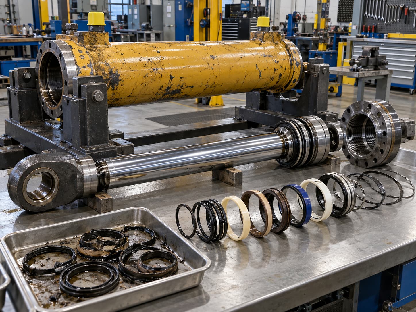
The term hydraulic ram is often used interchangeably with hydraulic cylinder, particularly for heavy lifting and mobile equipment. Regardless of terminology, the same principle applies: if a damaged piston rod, worn bore, misalignment, contamination, or pressure problem is left unresolved, installing new seals may only postpone the next failure.
For an unfamiliar cylinder, record all critical dimensions before machining or ordering parts. DALLAST's hydraulic cylinder measurement guide covers bore, rod, stroke, mounting geometry, ports, seal dimensions, and condition checks.
Disassembly, Inspection, and Dimensional Tolerances
A professional rebuild begins before the gland is removed.First identify the cylinder, machine, normal operating pressure, failure symptom and previous repair history. Photograph the entire cylinder, ports, mounts and rod before cleaning. Mark the relative orientation of components where orientation matters, and assign each major component an inspection number.
A practical reconditioning sequence is:
Isolate the machine, mechanically support suspended loads, shut down hydraulic power, relieve stored pressure and verify zero-energy condition. Drain the cylinder into an appropriate container, cap open lines, clean the exterior, photograph and mark components, then remove the gland or head, rod assembly, piston and seals according to the cylinder construction. Keep removed seals for failure analysis rather than immediately discarding them. Clean metallic components using a process compatible with the materials, then measure before deciding what can be reused.
OSHA 29 CFR 1910.147 requires hazardous stored or residual energy to be relieved, disconnected, restrained or otherwise rendered safe during covered servicing activities. Hydraulic pressure is specifically relevant stored energy.
What should be measured?
Use a micrometer for rod diameter, an inside bore gauge for barrel diameter and taper, a dial indicator with V-blocks or a suitable straightness fixture for the rod, a profilometer for surface roughness, and appropriate hardness equipment where rod or coating hardness is part of the repair specification.
| Inspection Point | Measurement Method | Practical Acceptance Approach |
|---|---|---|
| Rod straightness | V-blocks + dial indicator | Compare TIR/runout with original drawing or repair spec |
| Rod diameter | Micrometer at several axial/angular positions | Must remain within seal/bearing design diameter |
| Rod surface | Profilometer + visual inspection | Check Ra, scratches, pitting, chrome loss |
| Bore diameter | Dial bore gauge at multiple depths and axes | Record taper and out-of-round condition |
| Bore finish | Profilometer | Match piston-seal supplier requirement |
| Piston/gland clearances | Micrometer + bore gauge | Compare with drawing and wear-ring/seal design |
| Seal grooves | Caliper/micrometer | Verify width, depth, edge damage and extrusion gap |
| Threads and retaining features | Visual + gauges | No deformation, cracking or damaged locking features |
There is no universal rod-straightness rejection number for every repaired cylinder. As a useful new-material benchmark, Ovako specifies maximum straightness deviation of 0.1 mm per 0.5 m for Cromax rod below 30 mm diameter and 0.1 mm per 1 m for larger diameters. Those values are useful when evaluating replacement rod stock, but the cylinder OEM or engineering drawing remains the authority for an assembled repair. Ovako
The same caution applies to bore roundness. Measure the bore near the gland end, mid-stroke and cap end, with readings taken in at least two perpendicular directions. The difference reveals taper and ovality. The pass/fail value should come from the cylinder drawing, piston-seal geometry and allowable extrusion clearance rather than an arbitrary universal limit.
Single-acting cylinders require particular attention to the gravity- or load-return side, vent/breather condition and plunger surface. Double-acting cylinders require inspection of both pressure chambers and piston sealing surfaces because internal bypass can occur in either direction.
If the unit is being reverse-engineered for replacement rather than rebuilt, DALLAST also provides a more concise hydraulic cylinder dimension measurement guide.
Piston Rod and Seal Repair: Replace, Polish, Re-Chrome, or Manufacture a New Rod?
The piston rod is one of the most important decisions in a hydraulic ram rebuild because the rod surface is also the dynamic sealing surface.
Remove old rod seals, wipers, O-rings, backup rings and piston seals with non-damaging seal tools. Avoid scratching the gland groove or rod with screwdrivers or sharp picks. Before installing replacements, identify the original seal profile, ID, OD, width, groove dimensions, pressure direction and material.
Seal selection should be based on the actual hydraulic fluid, pressure, temperature, sliding speed, extrusion gap and environment.
| Seal Material | Typical Reconditioning Consideration |
|---|---|
| Polyurethane | Strong abrasion and extrusion resistance; widely used for rod and piston seals |
| PTFE compounds | Low friction and broad chemical resistance; often require energizers and controlled surface finish |
| FKM | Useful with many higher-temperature petroleum-fluid applications |
| NBR/HNBR | Common in mineral-oil hydraulic systems; compound limits vary |
| EPDM | Useful with certain water-based/phosphate-ester fluids but generally unsuitable for mineral petroleum oils |
Do not select seals from polymer name alone. Manufacturer-specific compounds can have substantially different temperature and fluid compatibility.
For example, Parker publishes polyurethane formulations extending to approximately 300°F for specific compounds, while its broader materials literature gives PTFE an extremely wide theoretical material-temperature range. Those figures should not be interpreted as the operating limit of every finished cylinder seal. Parker Discover
What surface finish should a repaired rod have?
SKF recommends approximately Ra 0.05–0.3 µm for many chrome-plated piston rods used with thermoplastic and rubber seals and 0.05–0.2 µm for PTFE materials. It also gives a typical chromium thickness of approximately 20–30 µm for the conventional induction-hardened/chrome-plated rod configuration.
Trelleborg gives a similar rod recommendation of approximately Ra 0.1–0.3 µm, with hard-chrome coating around 20–30 µm in the referenced configuration, while stressing that Ra alone cannot fully characterize a sealing surface. Material ratio and surface profile also matter. Trelleborg
Ovako Cromax rod stock provides another useful manufacturing benchmark: standard chrome thickness above 20 µm on most sizes, minimum chrome hardness of 850 HV0.1, and Ra below 0.2 µm.
These are excellent engineering reference values, not universal rebuild tolerances.
A practical rod decision matrix is:
| Rod Condition | Normal Repair Direction |
|---|---|
| Light staining or extremely shallow marks, dimensions intact | Controlled polishing may be sufficient |
| Localized chrome damage/pitting but base rod structurally sound | Strip, grind as required, hard-chrome plate and finish |
| Deep scoring into base material | Engineering review; re-chrome only if final dimensions and strength can be restored |
| Bent rod outside permissible straightness | Straighten only under an approved procedure or replace |
| Cracking, severe corrosion, extensive section loss | Replace rod |
| Previous weld repair in a highly stressed region | Evaluate metallurgy/fatigue risk before reuse |
Local weld build-up is not automatically an acceptable rod repair. Welding changes the heat-affected zone and may alter hardness, residual stress, straightness and fatigue performance. If welding is considered, the base steel grade, heat treatment and subsequent machining must be known.
For readers who need to understand how original rod machining, heat treatment and chrome finishing affect serviceability, link to DALLAST's hydraulic cylinder manufacturing process. The current page discusses induction hardening, grinding and hard-chrome finishing.
Cylinder Bore Restoration: Honing, Sleeving, Plating, or Barrel Replacement
Bore repair depends on both damage depth and how much material can be removed without invalidating the piston, wear-ring and seal geometry.
Light glazing or superficial marks may be corrected by controlled honing. Deeper longitudinal scoring requires measurement after honing to determine whether bore diameter, taper and roundness remain acceptable.
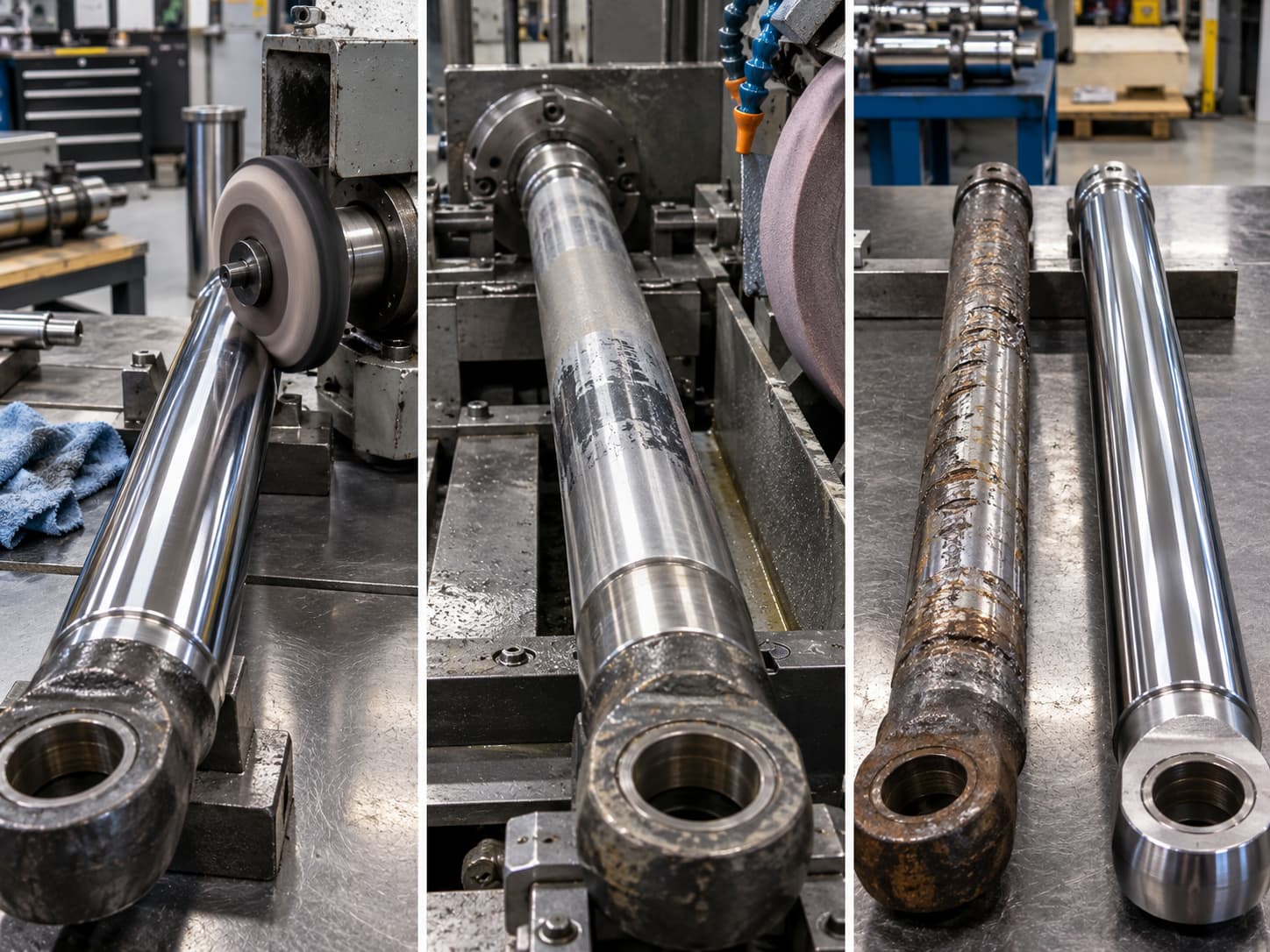
Hallite notes that honed tube around Ra 0.1–0.4 µm is generally suitable for many hydraulic sealing applications, while excessively smooth or excessively rough surfaces can both shorten seal life. Hallite
This is why simply honing until a scratch disappears can be a mistake: the bore may look better while becoming too large for the original piston-seal/extrusion geometry.
| Bore Condition | Typical Restoration Path | Key Acceptance Question |
|---|---|---|
| Glaze / very light scoring | Hone or controlled polish | Is final surface profile suitable for the seal? |
| Moderate scoring | Hone and remeasure | Does final diameter/taper remain within design limit? |
| Severe localized wear | Bore + engineered sleeve may be possible | Can wall strength and concentricity be maintained? |
| Extensive corrosion / deep pitting | Sleeve or replace barrel | Is the remaining parent tube structurally sound? |
| Bulged/cracked pressure tube | Replace barrel/cylinder | Do not treat structural damage as a surface repair |
Sleeving
Sleeving a hydraulic barrel is an engineering repair, not simply inserting a second piece of tube.
The parent barrel must have enough wall section to be machined safely. Sleeve outside diameter, interference or retention method, finished ID, concentricity, end retention and pressure loading must all be designed together.
There is no single universal interference-fit value. A fit suitable for a small thick-wall cylinder may be inappropriate for a large thin-wall pressure barrel. The interference should be calculated from diameters, materials, wall thickness, temperature and required contact pressure.
Likewise, welding a sleeve into a barrel can introduce distortion and residual stress. If welding is part of the approved design, machining and final dimensional verification should occur after welding, with stress-relief or heat-treatment decisions based on material and weld procedure.
What about internal plating?
Hard chrome and other engineered coatings may recover certain worn surfaces, but finished dimensions, coating adhesion, crack structure, corrosion environment and seal compatibility must all be controlled.
Do not promise a universal coating "life in years." Service life depends on pressure cycles, contamination, corrosion, side load, lubrication and coating condition.
Where repair would require excessive machining, a new barrel or complete replacement cylinder may offer lower risk and total cost. DALLAST's industrial hydraulic cylinders category confirms OEM/ODM capability for a range of industrial cylinders, providing a logical commercial destination for readers whose original ram is no longer economically repairable.
Reassembly, Fluid Handling, Pressure Testing, and Acceptance Criteria
Before reassembly, every component should have an inspection disposition: reuse, repair, replace or reject.
Clean the barrel, drilled oil passages, piston, gland and ports. Protect newly finished rod surfaces during assembly. Install seals in the correct direction using compatible assembly lubricant and installation tools that prevent twisting or cutting.
Do not publish one generic gland, piston-nut or tie-rod torque table as if it applies to all hydraulic rams.
Correct tightening torque depends on fastener diameter, thread pitch, strength grade, lubrication, coating, joint geometry and locking method. Where engineering calculation is required, the simplified relationship:
T ≈ K × F × D
can relate torque T, nut factor K, target preload F, and nominal diameter D, but K changes substantially with lubrication and surface condition. The original assembly drawing or approved repair specification should therefore control final torque.
Cleanliness and flushing
New oil is not automatically clean enough for a repaired hydraulic system. Flush hoses and test equipment, use filtered fill oil and establish the cleanliness target from the most contamination-sensitive component in the circuit.
As reference points, Parker identifies ISO 4406 20/18/15 with relatively general/low-pressure applications and 18/16/13 with higher-quality or higher-pressure systems; HYDAC likewise recommends determining the target from individual component requirements. These should be treated as application examples rather than one mandatory cylinder-rebuild specification. Parker Hannifin Corporation
Formal pressure-test procedure
A safe shop test stand should restrain the cylinder mechanically without side-loading it. Hoses, manifolds, gauges and fittings must be rated for the maximum test pressure. Instrumentation should include calibrated pressure measurement, oil-temperature measurement and, when internal leakage must be quantified, an appropriate low-flow meter or collection method.
Parker's telescopic-cylinder service manual provides a useful example of a manufacturer-defined test procedure: cycle the cylinder through at least three full cycles, then hold pressure for at least 30 seconds at 2,500 psi or the pressure specified on the assembly print, rejecting the cylinder for external leakage or structural deformation. Double-acting versions are tested in both directions. Parker also provides specific bypass criteria for those particular cylinder/seal designs.
That does not mean every rebuilt cylinder should be tested at 2,500 psi. A 1,500-psi cylinder must not simply be subjected to a 2,500-psi procedure copied from another manufacturer's manual. Test pressure, duration and allowable internal leakage must come from the applicable drawing, manufacturer procedure or engineering approval.
Field testing should normally be limited to functions that can be safely carried out with installed equipment and appropriate rated instrumentation. A workshop test stand provides better restraint, contamination control, controlled loading and repeatable leakage measurement.
If there is cracking, a bulged barrel, uncertain metallurgy, severe rod damage, questionable weld repairs or no reliable design pressure information, the safer commercial decision may be professional engineering evaluation or replacement rather than an improvised pressure test.
FAQ
What are typical piston-rod straightness and bore-roundness tolerances after reconditioning?
There is no universal tolerance covering every hydraulic ram. As a reference for new hard-chrome rod stock, Ovako specifies straightness as tight as 0.1 mm/1 m for many larger-diameter Cromax rods, while smaller diameters have a 0.1 mm/0.5 m specification. A rebuilt rod should ultimately meet the cylinder manufacturer's drawing or approved repair specification. Bore diameter, taper and roundness must similarly remain compatible with the piston, wear rings, extrusion gaps and seal design.
How should a reconditioned hydraulic ram be pressure tested?
Mount it securely on a rated test stand, connect rated hoses and calibrated instruments, bleed air, cycle at low pressure first, verify smooth travel, then increase to the approved test pressure and specified hold time. Inspect for external leakage and deformation and measure internal bypass where applicable. The actual test pressure and leakage limit must come from the cylinder specification-not from a generic percentage copied from another cylinder.
When should a piston rod be re-chromed rather than replaced?
Re-chroming is reasonable when the base rod remains structurally sound and can be restored to the specified diameter, straightness, surface finish and coating quality after stripping and machining. Replace the rod when there is severe section loss, cracking, unrecoverable bending, extensive deep corrosion, or when machining required for re-chroming would remove too much parent material.
Which seal materials work best with common U.S. hydraulic fluids?
Polyurethane, NBR/HNBR, PTFE and FKM are common options for mineral-oil hydraulic systems, but the correct choice depends on the exact fluid, temperature, pressure, speed and seal design. EPDM may be appropriate for certain water-based or phosphate-ester fluids but is generally inappropriate for petroleum/mineral oil. Always confirm the exact compound against the seal manufacturer's compatibility chart.
What tools are needed for professional hydraulic ram reconditioning?
Core inspection equipment normally includes outside micrometers, an inside bore gauge, dial indicator and rod-support fixture, surface profilometer, seal/groove measurement tools, appropriate hardness testing where required, cleaning equipment and calibrated pressure instrumentation. A professional shop additionally needs controlled lifting/holding fixtures, cylinder disassembly tooling, machining or honing capability and a properly engineered test stand.
Should I recondition a hydraulic ram or replace it?
Reconditioning usually makes more sense when the barrel, rod, mountings and pressure-containing structure remain serviceable and the principal work involves seals, bearings, light honing or economically recoverable rod damage. Replacement becomes more attractive with structural cracks, severe barrel damage, badly compromised rods, repeated failures, obsolete components, uncertain design data or when rebuild cost plus downtime approaches the cost of a correctly engineered replacement.