

A hydraulic system converts mechanical input into fluid power, then converts that fluid power back into force or motion. This combination of compact components and high force output makes hydraulics common in industrial presses, machine tools, construction and agricultural equipment, lifting systems, and mobile machinery.
Understanding the system takes more than knowing that a pump moves oil. Pressure develops in response to resistance, flow controls actuator speed, valves direct and regulate energy, and fluid condition affects reliability. This guide explains those relationships and follows the system from Pascal's law through circuit operation, sizing, maintenance, and troubleshooting.
Pascal's law and force transmission
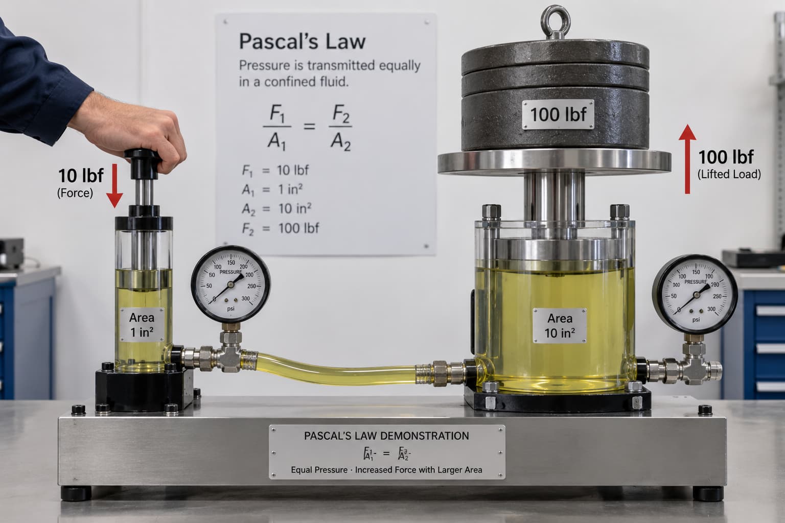
Hydraulic power is based on Pascal's law: pressure applied to a confined fluid is transmitted equally in all directions.
Hydraulic pressure is:
Pressure = Force ÷ Area
or:
P = F ÷ A
In U.S. customary units:
P = pressure in pounds per square inch (psi)
F = force in pounds-force (lbf)
A = area in square inches (in²)
Rearranging the formula gives:
F = P × A
This relationship explains hydraulic force multiplication. Consider two connected cylinders. The small piston has an area of 1 in² and the larger piston has an area of 10 in². If an operator applies 10 lbf to the small piston:
P = 10 lbf ÷ 1 in² = 10 psi
Approximately 10 psi also acts on the larger piston, producing a theoretical force of:
F = 10 psi × 10 in² = 100 lbf
The output is ten times the input because the piston area is ten times larger.
Actual systems are not 100 percent efficient. Seal friction, internal leakage, losses through valves and hoses, and mechanical friction reduce the available force. At 90 percent combined hydraulic and mechanical efficiency:
Actual force = 100 lbf × 0.90 = 90 lbf
The same method applies to industrial and mobile equipment. A cylinder with an effective area of 20 in² at a measured pressure of 2,500 psi produces:
Theoretical force = 2,500 × 20 = 50,000 lbf
At an estimated efficiency of 92 percent:
Usable force ≈ 46,000 lbf
When the effective piston area is known, a pressure-gauge reading can therefore provide an approximate cylinder force.
Pressure and flow are related but not interchangeable. Pressure determines the available force or torque, while flow mainly determines actuator speed.
Main hydraulic components
Each component has a specific role in generating, controlling, or using hydraulic energy.
Hydraulic pumps
The pump produces flow. Pressure develops when that flow encounters resistance.
| Pump type | Typical characteristics | Common applications |
|---|---|---|
| Gear pump | Simple, economical, rugged, fixed displacement | Mobile equipment, lubrication, general hydraulics |
| Vane pump | Smooth flow, relatively quiet, good efficiency | Industrial machinery, moderate-pressure systems |
| Piston pump | High pressure, high efficiency, variable displacement available | Heavy equipment, presses, precision systems |
A fixed-displacement pump delivers approximately the same volume with each revolution and suits systems with relatively constant demand.
A variable-displacement pump changes its output as demand changes. It is often used where energy efficiency, precise control, or varying actuator requirements matter.
Pump selection should account for displacement, rated pressure, maximum speed, required flow in GPM, volumetric efficiency, fluid compatibility, and mounting arrangement.
Reservoir
The reservoir stores fluid and gives air bubbles time to separate, contaminants time to settle, and heat a path to dissipate. A well-designed reservoir may include:
Fill and breather filters
Return-line diffusers
Suction strainers where appropriate
Level and temperature indicators
Internal baffles
Drain and cleanout access
Mobile equipment may need a compact pressurized reservoir or special baffling because it operates on slopes and under vibration.
Hydraulic valves
Valves control where hydraulic energy goes and how the actuator responds.
| Valve type | Main function |
|---|---|
| Relief valve | Limits maximum system pressure |
| Directional control valve | Sets actuator direction |
| Flow control valve | Controls actuator speed |
| Check valve | Allows flow in one direction |
| Pressure-reducing valve | Maintains lower pressure in a branch circuit |
| Sequence valve | Starts a second operation after a pressure threshold |
The relief valve protects pumps, hoses, cylinders, and other components from excessive pressure.
Actuators
Hydraulic actuators convert fluid power into mechanical output. A hydraulic cylinder creates linear movement as pressure acts on piston area. A hydraulic motor creates rotary movement: flow affects rotational speed, while pressure differential determines available torque.
Seals must match the fluid chemistry, pressure, speed, and temperature. Nitrile rubber is common in mineral-oil systems. FKM is often used at higher temperatures or in chemically demanding service, while PTFE-based elements may suit applications requiring low friction or broader chemical compatibility. Verify the final material against the actual fluid and operating conditions.
A typical hydraulic circuit
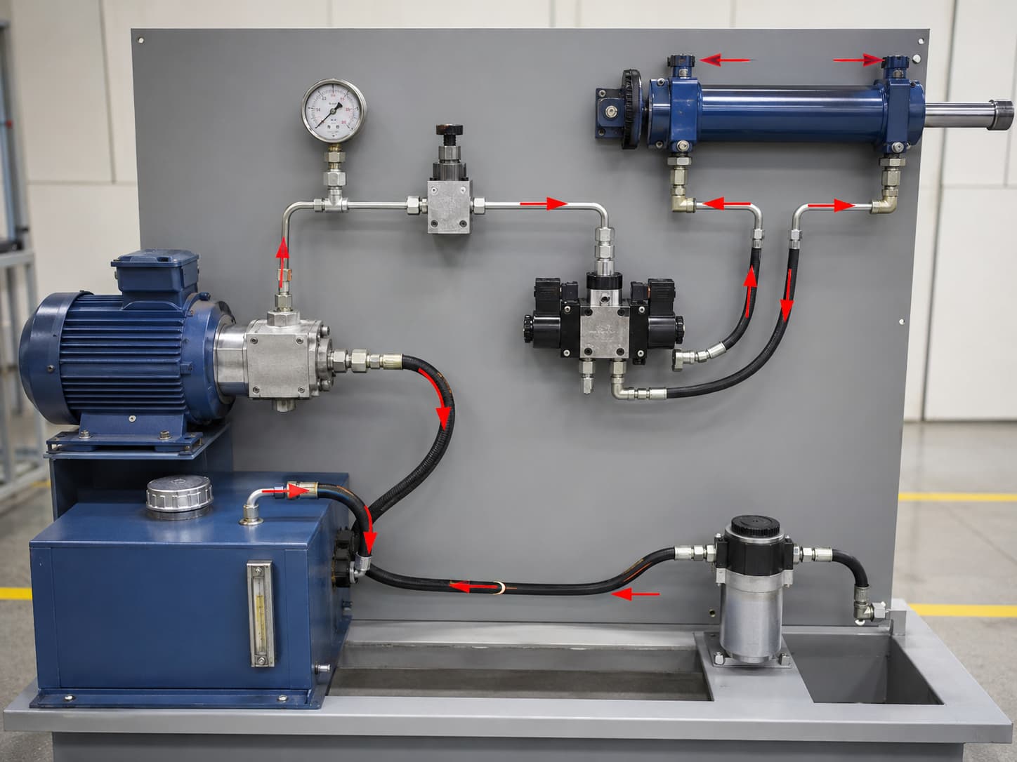
A basic industrial circuit can be shown as:
1. Startup
An electric motor or engine starts the pump. The pump draws fluid from the reservoir and sends it into the pressure line.
With the directional valve in an open-center or unloading position, flow may return to the reservoir at relatively low pressure. Useful monitoring points include pump outlet pressure, main-line flow, reservoir temperature, and return-filter differential pressure.
2. Pressure development
When the directional valve sends flow to the actuator, resistance increases. Pressure rises only enough to overcome the external load and internal losses.
If a cylinder needs 1,800 psi to move its load, for example, pressure may rise from a low standby level to approximately 1,800 psi plus the circuit losses.
3. Cylinder extension
The directional valve routes pump flow into the cylinder's cap end. Oil leaving the rod end returns through the valve to the reservoir, and the cylinder extends. A flow-control valve can restrict the flow to set extension speed.
4. End of stroke and pressure limiting
When the cylinder reaches the end of its stroke, it stops moving. If the pump continues to supply flow, pressure rises quickly.
At its preset pressure, the relief valve opens and diverts excess flow toward the reservoir. This prevents the system from exceeding its safe pressure limit. Operating continuously across the relief valve wastes energy and produces substantial heat.
5. Retraction
The directional valve reverses, sending pressurized oil to the rod side while oil from the cap side returns to the tank.
The rod reduces the effective piston area during retraction, so a conventional single-rod cylinder produces less retract force at the same pressure. With the same inlet flow, it may also retract faster.
6. Unloading and shutdown
After the operation, the circuit returns to neutral. Depending on its design, the pump may unload, destroke, or stop.
Before maintenance, release stored pressure according to the machine manufacturer's lockout/tagout and depressurization procedures.
Electrohydraulic systems allow technicians to compare the electrical command with the hydraulic response. A scope or diagnostic interface can confirm the command sent to a solenoid or proportional valve, while gauges and flow meters show what happened in the circuit.
If the PLC sends a valve command but pressure does not change, inspect the solenoid, spool movement, pilot circuit, and hydraulic supply. If there is no command, begin with the controller, sensor, wiring, or interlock.
Hydraulic fluid, pressure loss, and maintenance
Hydraulic fluid transmits power, lubricates components, carries heat away, transports contaminants to filters, and protects surfaces against wear and corrosion.
Mineral hydraulic oils are commonly identified by ISO viscosity grades such as ISO VG 32, 46, and 68. The correct grade depends on the pump requirements and operating temperature.
Cold oil becomes more viscous. If it is too thick, the system may experience difficult startup, high suction loss, slow actuator response, cavitation, or filter bypass.
High temperature reduces viscosity and may increase internal leakage, weaken the lubricating film, accelerate oxidation, and damage seals.
Equipment in cold northern U.S. climates may need a lower-viscosity fluid or one with a high viscosity index. Machinery running continuously in hot southern climates may need greater thermal stability or a higher operating-viscosity grade. Check the pump manufacturer's allowable viscosity range before changing the oil.
Pressure loss in the circuit
Fluid loses pressure as it travels through hoses, pipes, fittings, filters, coolers, and valves. The loss increases with flow rate, line length, fluid viscosity, restrictions, and inadequate hose diameter.
Pressure drop rises rapidly as flow velocity increases. Suction, pressure, and return lines should therefore be sized for an appropriate velocity, with losses checked against manufacturer data or hydraulic pressure-drop calculations.
Common external leak points include hose connections, rod seals, valve manifolds, pump shaft seals, fittings, and damaged tubing.
Maintenance practices
A practical maintenance program should include the following work:
Check fluid level, temperature, unusual noise, and visible leaks during routine inspections.
Use filter restriction indicators instead of relying only on calendar-based replacement.
Take oil samples from consistent locations under consistent operating conditions.
Test particle contamination, viscosity, water content, oxidation, and wear metals where appropriate.
Investigate significant changes in particle count instead of simply replacing components.
Inspect hoses for abrasion, cracking, blistering, and movement at the fittings.
Confirm chemical compatibility when replacing fluid or seals.
Oil and filter changes should follow the equipment manufacturer's recommendations, contamination monitoring, operating severity, and oil-analysis results rather than one universal operating-hour interval.
Hydraulic sizing and control
Sizing usually begins with the load force and required actuator speed.
Assume a machine needs 30,000 lbf from a cylinder at a maximum working pressure of 2,500 psi. The required piston area is:
A = F ÷ P
A = 30,000 ÷ 2,500 = 12 in²
Calculate the bore from:
A = πD² ÷ 4
Therefore:
D = √(4A ÷ π)
For an area of 12 in²:
D ≈ 3.91 in
A standard 4-inch bore is a reasonable starting point, subject to the safety factor, friction, pressure rating, mounting loads, and rod-buckling requirements.
A 4-inch bore has an area of approximately:
A = 12.57 in²
At 2,500 psi, its theoretical extension force is:
F = 2,500 × 12.57 ≈ 31,425 lbf
If the required extension speed is 4 in/s, the required flow is:
Q = Area × Velocity
Q = 12.57 × 4 = 50.28 in³/s
One U.S. gallon contains approximately 231 in³, so:
GPM = 50.28 × 60 ÷ 231 ≈ 13.1 GPM
The pump must supply approximately 13.1 GPM at the required pressure before allowing for efficiency and any simultaneous flow demand.
Setting the relief valve
The relief valve must protect the lowest-rated critical component while allowing the machine to develop its required working force.
Do not turn the adjustment screw until the machine appears to work harder. Identify the design pressure, verify the component ratings, connect a suitable calibrated gauge, load the circuit according to the approved service procedure, and adjust the valve within the manufacturer's specification.
Electrohydraulic controls
Modern systems may use proportional or servo valves controlled by a PLC, motion controller, or electronic amplifier.
Proportional valves provide variable flow or pressure control. Servo valves are generally used when very fast, precise response is required, although they demand cleaner fluid and more sophisticated controls.
Hydraulics generally provide higher force density and better load holding than pneumatics. Pneumatic systems can be cleaner, simpler, and economical for high-speed automation with lower force requirements, but compressed air is far more compressible than hydraulic oil.
Hydraulic troubleshooting checklist
Take measurements before replacing components.
Low force or loss of pressure
Verify the fluid level.
Measure pump outlet pressure.
Confirm the relief-valve setting.
Check whether the relief valve is stuck open.
Perform a pump flow test.
Check the cylinder or motor for internal leakage.
Inspect directional valves for internal bypass.
Slow actuator movement
Measure actual system flow.
Check filter restriction.
Verify pump speed.
Inspect the flow-control settings.
Check for internal leakage.
Measure pressure drop across hoses and valves.
Overheating
Check whether flow is passing continuously over the relief valve.
Confirm the oil level and viscosity.
Check cooler performance.
Measure internal leakage.
Inspect for undersized lines or restrictive valves.
Verify pump and valve efficiency.
Noise or cavitation
Check the reservoir level.
Inspect suction hoses for restrictions and air leaks.
Confirm oil viscosity at startup.
Check the suction strainer.
Inspect pump inlet pressure.
Look for foaming or aerated oil.
Using pressure gauges, temperature sensors, and flow meters in a logical sequence usually isolates a fault faster than replacing a pump or valve based only on symptoms.
Engineering and system support
A pump and cylinder sizing calculator with worked examples, a complete hydraulic circuit CAD package, and a structured performance assessment can help an engineering or maintenance team evaluate an existing or proposed installation.
Typical engineering deliverables include load and pressure testing, oil sampling, contamination analysis, a component-sizing review, circuit optimization, and system reviews based on applicable ISO 4413 and SAE guidance.
On a commercial website, give engineers three direct routes: download the sizing calculator, request circuit drawings, or schedule an equipment assessment through a form, phone contact, or local distributor. State the expected response time and specify which files or test reports the customer will receive.
Frequently asked questions
How does Pascal's law multiply force, and how is it calculated in psi and in²?
Pressure applied to confined hydraulic fluid is transmitted throughout the fluid. Use P = F ÷ A to calculate pressure and F = P × A to calculate output force. Applying 10 lbf to a 1 in² piston creates 10 psi. That pressure acting on a 10 in² piston theoretically produces 100 lbf.
What is the difference between gear, vane, and piston pumps?
Gear pumps are rugged, economical, and common in fixed-displacement applications. Vane pumps generally run more smoothly and quietly in industrial systems. Piston pumps provide high pressure and efficiency and are often used where variable displacement or more advanced control is required.
How does a typical hydraulic circuit operate?
The pump draws oil from the reservoir, and the directional valve sends flow to the actuator. Pressure rises in response to the load as the cylinder extends or retracts. The relief valve limits excessive pressure. After the operation, the valve returns to neutral and the pump unloads, destrokes, or stops according to the circuit design.
How do I choose hydraulic fluid?
Start with the equipment manufacturer's viscosity requirements. Then consider the minimum startup temperature, normal operating temperature, viscosity index, anti-wear requirements, oxidation resistance, water exposure, seal compatibility, and environmental conditions. ISO viscosity grade alone is not enough.
What are the most common hydraulic system failures?
Common problems include overheating, cavitation, excessive noise, slow actuator movement, inability to build pressure, internal or external leakage, contaminated oil, and valve faults. Begin troubleshooting with measurements of fluid condition, pressure, flow, and temperature.
How do I size a pump and cylinder for force and speed?
Calculate the cylinder area with A = F ÷ P, then convert that area to bore diameter using D = √(4A ÷ π). After selecting the cylinder, calculate the flow needed for the target speed:
GPM = Area (in²) × Speed (in/s) × 60 ÷ 231
Before selecting the pump and cylinder, account for efficiency, duty cycle, simultaneous actuator demand, pressure loss, component ratings, and an appropriate safety margin.